
Views: 0 Author: Site Editor Publish Time: 2026-09-15 Origin: Site


Modern hardware architectures demand increasing density and complexity. Component selection dictates overall system viability from the very first schematic draft. Choosing the wrong architecture leads to severe consequences down the line. You might face thermal bottlenecks that throttle performance. Signal integrity failures can cause erratic system behavior. Compliance issues often delay product launches. Bill of Materials cost overruns threaten project feasibility entirely. Hardware engineers and procurement teams need a reliable technical evaluation framework. We built this guide to help you navigate the primary categories of semiconductor components. You will learn how to assess architectural trade-offs across different device families. We will show you how to align component capabilities with strict project success criteria.
Application Dictates Architecture: The choice between standard logic, microcontrollers, and ASICs hinges on the balance between time-to-market, Non-Recurring Engineering (NRE) costs, and production volume.
Power Management is Mission-Critical: Modern electronics require precise thermal and efficiency controls; selecting the right DC-DC regulator or PWM controller is as critical as the core processor.
Mixed-Signal Complexity: Bridging analog inputs with digital processing requires rigorous evaluation of resolution, sampling rates, and noise immunity.
Supply Chain Resilience: Technical specifications must be weighed against component availability, lifecycle status, and the feasibility of second-sourcing.
An integrated circuit exists as a monolithic semiconductor substrate. It contains millions of interconnected active and passive devices. Transistors, resistors, and capacitors sit etched onto a single piece of silicon. This microscopic arrangement forms the core logic and power handling capabilities. Semiconductor foundries use photolithography to build these structures layer by layer. The resulting silicon die acts as the brain or muscle of the electronic system. Understanding this internal architecture helps engineers predict component behavior under stress. When you push a component near its maximum voltage rating, the internal dielectric layers experience immense strain. Over time, this causes electromigration, where metal atoms physically move and degrade the internal traces.
The physical package surrounding the silicon die matters immensely. Packaging impacts thermal dissipation directly. It dictates the PCB footprint and influences manufacturing complexity. Quad Flat No-Lead (QFN) packages offer excellent thermal performance. They feature a large exposed metal pad on the bottom that solders directly to the PCB ground plane. This pulls heat away from the silicon die efficiently. However, QFNs require precise solder paste application during assembly. Too much paste causes the component to float and misalign. Too little paste creates voids that ruin thermal transfer.
Ball Grid Array (BGA) packages provide high pin counts in small areas. They route signals through an array of solder balls beneath the component. This allows for massive I/O density, making them standard for high-performance processors. They demand X-ray inspection to verify solder joint integrity since you cannot see the connections visually. Small Outline Integrated Circuit (SOIC) packages consume more board space. They feature gull-wing leads extending from the sides. They remain easier to prototype, probe with an oscilloscope, and inspect manually.
Evaluate components beyond their raw silicon capabilities. Look at how the physical package integrates into the broader PCB ecosystem. Consider automated assembly line constraints early in the design phase. A powerful processor fails if the chosen package cannot dissipate heat. It also fails if your contract manufacturer struggles to solder it reliably. Align the physical package with your manufacturing capabilities and thermal budgets. Check the Moisture Sensitivity Level (MSL) rating on the datasheet. High MSL ratings mean the components absorb ambient humidity quickly. If not baked before reflow soldering, trapped moisture expands and cracks the package.
Microprocessors (MPUs) offer high compute power for complex operating systems like Linux. They rely entirely on external memory and peripherals. You must route high-speed memory buses to external DDR chips, which requires strict trace length matching and impedance control. Microcontrollers (MCUs) integrate memory and peripherals internally on the same die. They provide deterministic execution for dedicated embedded tasks. You write bare-metal C code or use a Real-Time Operating System (RTOS) to manage specific hardware functions.
Digital Signal Processors (DSPs) handle specialized digital workloads. They optimize high-speed, real-time mathematical operations. Audio filtering, video compression, and complex sensor arrays require DSPs. They feature dedicated Multiply-Accumulate (MAC) units that execute complex math in a single clock cycle. Evaluate these processors using strict success criteria. Check maximum clock speed against required processing throughput. Verify I/O availability for all required external sensors. Ensure hardware multipliers exist for intensive math operations. Analyze sleep and deep-sleep power consumption states.
A standard Digital logic IC handles essential board-level tasks. It performs logic level shifting between different voltage domains. For example, translating a 3.3V sensor signal to a 1.8V processor input. It manages simple state machines and acts as glue logic between major components. You must weigh architectural trade-offs during selection. Discrete logic components offer simplicity and low cost. They work well for basic AND/OR gating or signal buffering.
Consolidating discrete logic into a Complex Programmable Logic Device (CPLD) saves board space. Field Programmable Gate Arrays (FPGAs) offer massive logic consolidation. They allow you to define custom hardware architectures in software using languages like Verilog or VHDL. They reduce BOM line items but increase programming complexity. FPGAs require external configuration memory to load their logic state at boot, adding another component to your board.
Memory architectures divide into volatile and non-volatile categories. Volatile memory includes Static RAM (SRAM) and Dynamic RAM (DRAM). They lose data when power drops. SRAM offers incredibly fast access times and does not require constant refreshing, making it ideal for processor caches. DRAM provides massive storage density at a lower cost but requires a memory controller to constantly refresh the data cells.
Non-volatile options include Flash memory and EEPROM. They retain data without power. SPI NOR Flash provides reliable boot code storage with fast read speeds. NAND Flash offers high-density storage for file systems but requires wear-leveling algorithms to manage bad blocks. Base your memory selection on specific application requirements.
Evaluate data retention requirements for long-term storage.
Compare read and write speeds against processor bus speeds.
Check endurance cycles for applications requiring frequent data logging.
Assess power consumption during active read/write operations.
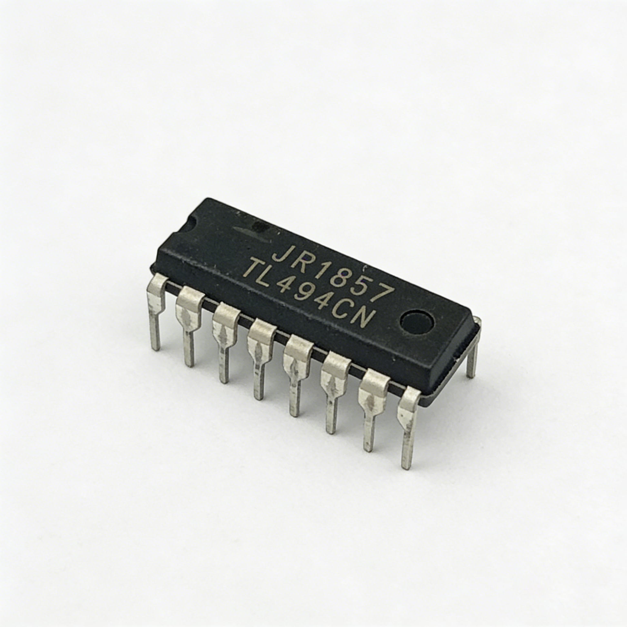
Operational amplifiers (Op-Amps) condition raw analog signals. Evaluate these analog components using specific datasheet parameters. Check the bandwidth to ensure it covers your signal frequency. Analyze the slew rate for fast-changing signals. A low slew rate distorts high-frequency square waves into triangles. Review the input offset voltage to prevent measurement errors. Even a few millivolts of offset can ruin a precision sensor reading.
Check noise figures to maintain signal integrity. Amplifying low-level sensor data in noisy environments presents severe challenges. Proper grounding techniques become mandatory. Shielding sensitive analog traces prevents electromagnetic interference from corrupting the data. Use differential signaling whenever possible. Differential amplifiers reject common-mode noise picked up along the trace routing.
Foundational utility components maintain enduring relevance in modern hardware. The classic 555 timer and discrete oscillators handle basic timing functions. They generate reliable pulses for simple control circuits. Decide when to use these discrete analog components carefully. Sometimes integrating timing functions directly into an MCU saves valuable board space. Discrete oscillators offer higher precision for strict timing requirements. Crystal oscillators provide parts-per-million accuracy necessary for RF communications and real-time clocks. Integrated MCU timers reduce BOM cost for less critical timing applications like LED blinking or basic debouncing.
Mixed-signal components bridge the physical and digital worlds. Analog-to-Digital Converters (ADCs) translate real-world voltages into binary data. Digital-to-Analog Converters (DACs) translate binary data back into physical voltages. Successive Approximation Register (SAR) ADCs offer excellent balance between speed and resolution for general data acquisition. Delta-Sigma ADCs provide massive resolution for low-frequency signals like temperature or weight scales. Use a strict decision matrix for ADC and DAC selection.
Evaluation Parameter | Technical Significance | Application Example |
|---|---|---|
Resolution (Bits) | Determines the smallest detectable voltage change. Higher bits mean finer granularity. | High-precision medical sensors require 24-bit ADCs to detect microvolt changes. |
Sampling Rate (Msps/Gsps) | Dictates how fast the converter captures the signal. Must satisfy Nyquist theorem. | Radar and radio frequency systems need Gsps speeds to capture fast waveforms. |
Interface Type (SPI, I2C, Parallel) | Affects data transfer speed and PCB routing complexity. | Parallel interfaces offer speed but consume many pins. SPI offers a fast serial alternative. |
Signal-to-Noise Ratio (SNR) | Measures the ratio of the desired signal to background noise. | High-fidelity audio equipment demands DACs with exceptional SNR ratings. |
Power management determines system stability. A DC-DC regulator IC steps down (buck) or steps up (boost) voltages. Different subsystems require specific, stable voltage levels. A 12V input might need stepping down to 5V for sensors, 3.3V for logic, and 1.2V for a processor core. Compare linear regulators (LDOs) against switching regulators. LDOs offer exceptionally low output noise. They generate significant heat when dropping large voltages. If you drop 12V to 3.3V at 1 Amp using an LDO, you dissipate 8.7 Watts of pure heat.
Switching regulators provide high power efficiency. They rapidly switch current through an inductor and capacitor network. This produces higher output noise and voltage ripple. Use LDOs for noise-sensitive analog circuits like RF transceivers or precision ADCs. Use switching regulators for high-current digital processors where efficiency matters more than microvolt-level ripple.
Pulse width modulation drives modern power electronics. A PWM power control IC governs switching regulators. It also manages dedicated motor controllers. It modulates pulse widths to achieve precise voltage regulation. It controls motor speed and torque effectively without wasting energy as heat. Evaluate the switching frequency carefully. Higher frequencies allow smaller inductors and capacitors, saving board space. However, higher frequencies increase switching losses in the MOSFETs, reducing overall efficiency.
Check the transient response for systems with rapidly changing loads. When a processor wakes from sleep, it demands a sudden spike in current. The power controller must react instantly to prevent voltage droop. Consider whether the controller requires integrated or external MOSFETs. Integrated MOSFETs save space for low-current applications. External MOSFETs handle massive currents and spread thermal dissipation across a larger PCB area.
System-level PMICs integrate multiple voltage regulators into one package. Highly integrated PMICs suit space-constrained, battery-powered devices like wearables or smartphones. They consolidate the BOM significantly. You get multiple buck converters, LDOs, and battery charging logic in a single chip. Discrete power management components offer layout flexibility. They spread heat across the PCB rather than concentrating it in one spot. Weigh BOM consolidation against routing complexity. A single PMIC simplifies procurement but complicates PCB trace routing, forcing you to route multiple power rails out of a single, dense BGA package.
Standard components dominate most hardware designs. The pros include immediate availability from multiple distributors. You can buy them off the shelf today. They offer proven reliability across thousands of deployments. They carry zero Non-Recurring Engineering (NRE) costs. The cons involve design compromises. They may require more board space than a custom solution. They often consume more power due to unneeded, active features on the die. You must adapt your design to the component's limitations. If a standard MCU lacks a specific hardware interface, you must add an external bridge chip.
An ASIC becomes financially and technically viable under specific conditions. You need ultra-high volume production to justify the investment. Strict Intellectual Property (IP) protection might demand custom silicon. If your algorithm is baked into the silicon, competitors cannot extract it easily. Extreme form-factor constraints also justify an ASIC approach. Medical implants require absolute miniaturization that standard parts cannot achieve.
Understand the implementation risks clearly. High upfront NRE costs deter many projects. Mask sets for modern silicon nodes cost millions of dollars. Long development cycles delay product launches significantly. It takes months to design, simulate, and fabricate the first prototypes. Silicon respin risks add financial pressure if the first design fails. If you find a bug in the silicon, you must pay for a new mask set and wait months for the next batch.
Evaluate dynamic and static power consumption rigorously. Dynamic power scales with clock frequency and switching activity. Every time a transistor switches, it charges and discharges internal capacitance, consuming power. Static power stems from transistor leakage currents. Even when idle, modern small-node transistors leak small amounts of current. Compare total power consumption against processing throughput. Measure it against signal bandwidth for analog parts. Battery-powered devices require components with exceptional performance-to-power ratios. Select components that complete tasks quickly and return to deep sleep states immediately.
Calculate junction temperatures accurately before finalizing the schematic. Ensure the chosen package dissipates heat effectively. Review the thermal resistance in the datasheet. This metric tells you how many degrees the silicon will rise above ambient temperature for every watt of power dissipated. The component must survive within the intended physical enclosure. Enclosures trap heat, raising the ambient temperature around the PCB. Add thermal vias and copper pours to your PCB design. These features pull heat away from high-power components and spread it across the internal ground planes.
Technical perfection means nothing if you cannot buy the part. Check the lifecycle status carefully on manufacturer websites. Avoid components marked NRND (Not Recommended for New Designs). Identify pin-compatible alternatives early in the schematic phase. Second-sourcing prevents production halts during global shortages. Ensure your firmware can handle slight variations between alternate components.
Follow these strict evaluation steps when selecting your primary components:
Define the absolute maximum voltage and current ratings required by the subsystem.
Filter available components by package type, eliminating packages your assembly house cannot handle.
Calculate the thermal dissipation based on your expected load and ambient enclosure temperature.
Verify the component lifecycle status and identify at least two pin-compatible alternatives.
Review the errata sheet for known silicon bugs before committing to the part.
High-speed digital components generate electromagnetic interference (EMI). Switching power components also create severe EMI. Fast edge rates cause signal reflections on improperly terminated traces. Mitigate these risks through strict layout practices. Place decoupling capacitors as close to the power pins as possible. Use small package sizes like 0402 for decoupling to minimize parasitic inductance. Design solid, uninterrupted ground planes beneath high-speed signals. Never route a high-speed trace over a split in the ground plane.
Adhere strictly to datasheet layout guidelines for switching regulators. Keep high-current loops as small as physically possible. The loop formed by the input capacitor, the switching MOSFET, and the diode acts as an antenna. Minimizing this loop area drastically reduces radiated EMI.
Designing around a proprietary, single-source component creates massive risk. If the manufacturer discontinues the part, your product line stops. Mitigate this through modular design approaches. Isolate proprietary components on separate daughterboards if possible. Monitor component lifecycles proactively using supply chain software. Build relationships with Field Application Engineers (FAEs) to get early warnings about end-of-life announcements. Secure Last Time Buy (LTB) agreements to stockpile inventory while you redesign the board.
Download and thoroughly review the full datasheets and errata documents for all shortlisted components.
Define strict power and thermal budgets using system-level block diagrams before drawing any schematics.
Execute SPICE simulations for critical power delivery networks and sensitive analog signal paths.
Order manufacturer evaluation boards to validate your architectural assumptions and begin firmware development immediately.
A: Digital components process discrete voltage levels, typically representing binary ones and zeros. Analog components handle continuous signal processing across an infinite range of voltages. Digital is ideal for computation and state machines, while analog excels at interfacing with real-world sensors, radio frequencies, and audio signals.
A: Use a switching regulator in high-current or high-voltage-drop scenarios. They offer significantly higher efficiency than Low Dropout (LDO) regulators. LDOs dissipate excess voltage as pure heat, making them unsuitable for large voltage step-downs. Switching regulators minimize thermal output, preserving battery life and reducing cooling requirements.
A: Pulse width modulation minimizes power loss across switching components and motor drivers. Instead of continuously restricting current like a variable resistor, it rapidly switches power fully on and fully off. This reduces the time transistors spend in their active, heat-generating region, maximizing overall energy efficiency.
A: Mixed-signal components combine analog-to-digital converters, digital-to-analog converters, and digital processing on a single die. This integration significantly reduces the PCB footprint. It lowers the overall BOM cost and minimizes signal routing complexity, reducing the chance of digital noise corrupting sensitive analog traces.
A: Base your choice on automated assembly capabilities, thermal pad requirements, and space constraints. BGA packages save space and offer high pin counts but require expensive X-ray inspection. SOIC and QFP packages are easier to prototype, probe, and inspect manually but consume significantly more board area.
A: NRND stands for "Not Recommended for New Designs." It indicates the manufacturer plans to phase out the component soon. Selecting an NRND part introduces severe supply chain risks, potentially forcing a costly PCB redesign and firmware rewrite when the component becomes completely obsolete.
A: Digital Signal Processors are necessary for applications requiring continuous, high-speed mathematical calculations. They feature specialized hardware multipliers optimized for tasks like audio filtering, video processing, and real-time sensor array analysis. These intense mathematical workloads would overwhelm a standard microcontroller's general-purpose architecture.


